

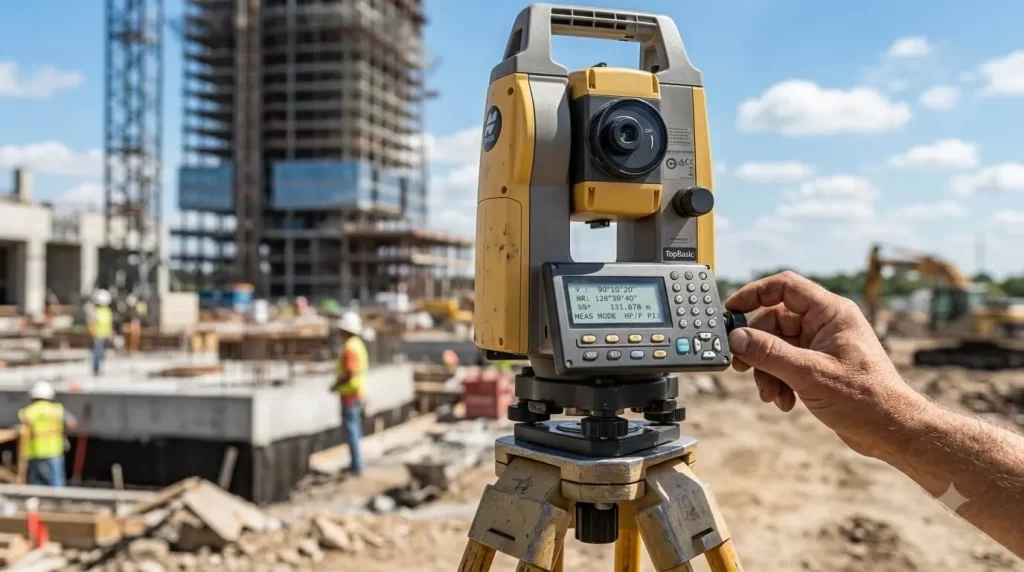
Total stations are the indispensable backbone of modern geospatial surveying, boundary establishment and site layout. It is integrated with an Electronic Distance Meter (EDM), electronic digital theodolite and on-board microprocessing to produce millimeter accuracy results in demanding field conditions.
But even the most sophisticated land surveying equipment is only as accurate as its setup and field execution. A small displacement at the instrument station can be added up to a large position error over a closed traverse.
As you evaluate the investment of a total station price or are working in the field, mastering error prevention is crucial to have the most accurate surveys and quality data.
The 3 Fundamentals of Total Station Errors
Errors encountered during a total station survey fall into three primary categories:
Instrumental Errors: Mechanical, optical, or electronic misalignments built into or developed within the device over time.
Personal / Setup Errors: Human oversights during levelling, targeting, data entry, or prism handling.
Environmental Errors: Atmospheric pressure shifts, heat shimmer, refractivity, and physical tripod settlement.
Below is an in-depth breakdown of these errors, their mathematical impacts, and proven field solutions.
1. Instrumental Errors & Calibration Solutions
A. Error of Horizontal Collimation (Mistake of Line of Sight)Cause: The optical axis of the telescope is not perpendicular to the axis about which it tilts ( trunnion axis ). When the telescope is tilted up and down, this misalignment causes horizontal angular deviations.The Answer:Face 1 / Face 2 Measurement Observations made in both Direct (Face 1) and Reverse (Face 2) modes cancel the horizontal collimation error when averaged.Digital Calibration: Before critical site work, run the internal electronic collimation routine built into modern instruments.
Correct Angle = (Face 1 Reading + (Face 2 Reading + or – 180 degrees))/2
B. Vertical Indexing FaultThe Cause: When the $0^\circ – 180^\circ$ reference line of the vertical circle does not coincide exactly with the true vertical. This systematic error biases the calculations of zenith angle and elevation.The Answer:Elevation control using two-face observations.6.2.1.2 Calibrate the instrument’s electronic dual-axis compensator on a level, stable surface before beginning field operations.
C. Error of the Tilting Axis (Trunnion Axis Error)The Cause: When the tilting axis is not perpendicular to the main vertical axis, it causes a horizontal error when sighting steep targets such as high rise structures.The Solution: Two-face measurements mathematically eliminate this mistake. If you are doing single-face measurements, run the total station’s stored tilt compensation calibration.
2. Setup & Personal Errors (Human Factors)
Misalignment and levelling errors
The Cause: The off-center condition relative to a control point is a prime source of angular error. An error of only 3 mm on a short backsight of 30 m introduces more than 20 seconds of angular error.
The Solution:Employ a two-stage levelling process: level the circular bubble first and then adjust using the electronic plate level.Check the laser or optical plummet periodically by flipping the instrument $180^\circ$ over a known benchmark point to verify that the beam is still centered.
Prism offsets and constant errors
The Cause: Prisms have different optical reflection points from their physical mounting points. A $0\text{ mm}$ target with a $-30\text{ mm}$ measurement adds 30 mm of error to every distance measurement, and this mistake is not recognized.
The Solution:All prisms are explicitly labeled with their physical offset value ($0\text{ mm}$, $-17.5\text{ mm}$, $-30\text{ mm}$).Make sure the prism profile setting on your data collector matches the target in use.
Erroneous Target Heights & Unplumbed Poles
The Cause: Hand-held prism poles are easily knocked out of plumb, especially in the wind or on uneven ground, resulting in skewed coordinates.
The Solution:
- Use bi-pods or tri-pods to hold target poles when doing precision control work.
- Recheck and write down changes in Target Height (HT) and Instrument Height (HI) in your field notes immediately.
3. Environmental & Atmospheric Corrections
Refraction and Scale Errors in the Air
The Cause: EDM-distance measurements are based on the time-of-flight or phase shift of light. Temperature and barometric pressure changes change the density of the air and change the speed of light and cause errors in distance scales over long ranges.
The Solution:
Measure the temperature and barometric pressure of the field and enter the current values in the Atmospheric Correction (PPM – Parts Per Million) menu of the total station.
Ground Refraction (Thermal Haze)
The Cause: Light rays bend randomly when they pass through layers of hot air near asphalt, concrete or bare ground. This disturbs sights and causes signal fluctuation in EDM.
The Solution:
- Maintain a sight line minimum of 1 meter above heat-radiating surfaces.
- Conduct the high precision control surveys in the early morning hours before the heating of the ground creates heavy thermal scintillation.
Summary Matrix: Errors, Impacts, and Fixes
| Error Category | Specific Error | Impact on Survey Data | Field Solution |
| Instrumental | Horizontal Collimation | Horizontal angle errors on inclined sights | Shoot in Face 1 & Face 2; execute electronic calibration |
| Instrumental | Vertical Index Drift | Systematic elevation & zenith angle errors | Dual-axis compensator adjustment; FL/FR averaging |
| Operational | Incorrect Prism Offset | Fixed distance offset on every measurement | Verify prism constant settings in software before shooting |
| Operational | Off-Center Setup | Positional drift across traverse network | Calibrate optical/laser plummet; perform 2-stage levelling |
| Environmental | Temperature / Pressure Shifts | Distance scale errors over long shots | Input current PPM atmospheric correction values |
Choosing the Right Land Surveying Equipment
Choosing the right equipment is about matching the capabilities of the equipment with the precision needs of the job site and the productivity goals of the crew.
Types of Instruments
1. Digital Level & Auto Level Standard
Application: Elevation Transfer, Run Levelling, Site Grading and Elevation Control
Key Feature: Automatic compensators maintain horizontal line of sight; reliable, cost effective baseline heighting tools such as a dedicated sokkia auto level.
2. Manual Total Stations
Use Case: Cadastral mapping, surveying boundaries, topology and basic constructions.
Key Feature High optical clarity, 2 axis compensation and direct reflectorless distance measurement.
Use Case: High speed construction stakeout, single-person operation, structural monitoring, and complex engineering layouts.
Key Feature: CAD workflows from field to office, auto-track motors, and target search algorithms.