

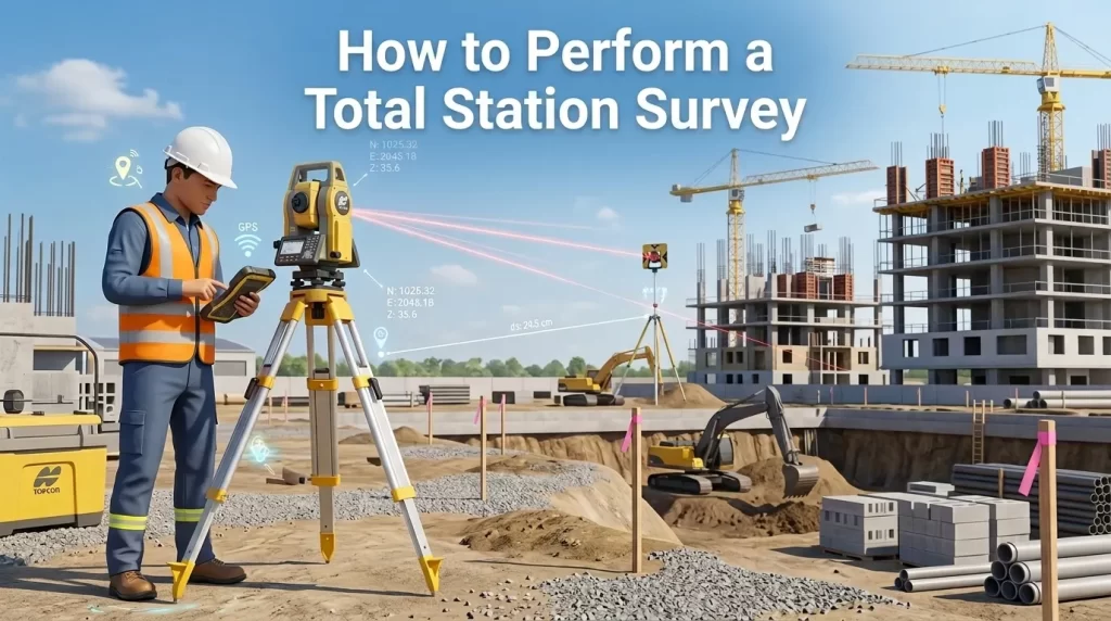
Total stations are the backbone of modern land surveying, construction layout, and topographic mapping. It combines an electronic theodolite (measuring horizontal and vertical angles) with an electronic distance meter (EDM) so that angles, distances, and coordinates can be recorded with millimeter precision using one instrument. Learning the basics of total station setup and use: This guide is for students, civil engineers, and construction professionals.
This guide takes you through each phase of a total station survey—from pre-survey planning to final data processing—so you do accurate, defensible fieldwork every time.
What is a total station, and why is it important?
A total station is an optical-electronic instrument used to measure the angles and distances between points on the ground. It stores this information as digits and calculates the coordinates in real time, and—in modern robotic models—it can even follow a prism independently. Total stations are utilized in:
Cadastral and boundary surveys
Topographic Map
Construction staking and layout
Surveys for monitoring (deformation, settlement)
As-built surveys Design support for roads, bridges and infrastructure
Total station surveying is faster and more accurate than older methods involving separate theodolites and tapes, and it provides data that is almost immediately ready for use in CAD or GIS software.
Step 1: Pre-Survey Planning and Reconnaissance Survey
Good survey work starts with planning before you take the tripod out of the bag.
Define the purpose of the survey—boundary survey, topo survey, construction layout, etc. This will determine how precise and how point-dense you need to be.
Collect existing control data—obtain known coordinates of benchmarks, control points, or reference monuments from previous surveys, government records, or GPS/GNSS observations.
Site reconnaissance – walk the site to identify obstructions, ideal instrument setup locations, and lines of sight between control points.
Verify equipment—check that the total station, tripod, prisms, batteries, data collector, and reflector poles all work and are fully charged.
Verify calibration status—ensure that the instrument has been recently checked for collimation error and that the correction constants (prism constant and atmospheric correction) are recorded.
A little planning here saves hours of rework in the field.
Step 2: Configuring the Total Station
The most important factor in survey accuracy is the correct configuration of the instrument. Errors here will be propagated to all subsequent measurements.
2.1 Setup over Point
Open the legs of the tripod and set it approximately over the survey point (station), leveling the tripod head by eye as closely as possible.
Secure the total station to the tripod head with the center screw.
Look through the optical or laser plummet and set the tripod legs until the plummet mark or laser dot is directly on the ground point.
2.2. Leveling the Instrument
Use the tripod’s leveling screws (usually three of them) to center the circle (bulls-eye) bubble.
Rotate the instrument so that the tube/plate is parallel to two of the leveling screws and adjust these two screws until the bubble is centered.
Turn the instrument 90° and use the third screw to fine-tune it in this direction.
Repeat until the bubble stays centered as you rotate the bottle 360 degrees.
Verify the optical plumb again—leveling can move the instrument slightly off the ground point. If necessary, loosen the tripod head and slide the total station (do not rotate) to re-center.
2.3 Power-On and Instrument Checks
Turn on the total station and let it complete its self-check/initialization.
If your model requires manual EDM correction, input atmospheric data (temperature and pressure).
Set the prism constant to the reflector you are using.
Verify that the instrument’s internal compensator (dual-axis tilt sensor) indicates the instrument is within tolerance.
Step 3: Determining Station Coordinates and Orientation
The total station must know its location and orientation before recording meaningful coordinates.
Known point setup: Enter the (Easting, Northing, Elevation) coordinates of the point that you are set up on, typically from a control point database.
Backsight orientation: Sight a second known point (the backsight) and enter its coordinates, or input a known bearing/azimuth. The instrument uses the backsight to set its internal zero-angle direction to true north or grid north.
Instrument height: Measure and record the height of the instrument above the ground point (HI). Record the target/prism height for each shot.
Resection method (alternative). If you aren’t set up on a known point, then you can use a resection—observing two or more known points from an arbitrary station location. The onboard software of the total station will automatically calculate your position and orientation.
Confirm with a checkup. When you have oriented yourself, if you have a third known point, take a sight on it and verify that the coordinates you see are within tolerance of the coordinates you have. This catches set-up errors before they pollute your entire dataset
Step 4: Field Measurements
Now that the station is oriented, you are ready to collect data.
Position the prism or reflector at the point to be measured, ensuring it is plumb using a bipod, tripod, or a hand-held pole equipped with a bubble level.
Look through the telescope at the target, with the crosshairs exactly on the prism.
Measure: Initiate the angle and distance measurement. The total station measures horizontal angle, vertical angle, and slope distance simultaneously and then calculates the 3D coordinate of the point.
Record properties: Assign a point code or description (e.g., “EP” for edge of pavement, “TREE,” or “MH” for manhole) so the data is usable later in CAD/GIS.
Repeat systematically across the site following a logical path (e.g., along features, grid lines, or breaklines for topographic surveys) to ensure complete coverage in an organized manner.
If you need to cover a larger area or if the line of sight is blocked, move to a new station. Set up a new station, backsight to the previous one (or another known point), and continue. Always tie back into control for accuracy checks.
Tips on Accurate Shots
When taking each shot, always double-check that the entered prism height matches the actual pole height.
Take face-left and face-right (direct and reverse) readings for critical control points to cancel instrument errors.
Avoid shots through heat shimmer, heavy rain, or over long grass, which may block the laser/optical path.
Step 5: Construction Stakeout (if needed)
However, if the goal of the survey is to establish design points on the ground, instead of recording existing conditions, the workflow is reversed:
Load design coordinates (from CAD/BIM) into the total station data collector.
Select a point to locate; the instrument indicates the direction and distance to move the prism to it.
Guide the rodperson left/right and in/out until the prism is at zero offset.
Mark the location on the surface (stake, nail, or paint) and record the “as-staked” coordinates for quality control.
Step 6: Closing the Survey and Verifying Accuracy
Before we pack up:
Close your traverse—if you have moved between multiple setups, tie back into a known control point to verify for closure error.
Compare redundant observations—check shots and duplicate measurements should agree within the tolerance specified for your project (typically a few millimeters to a couple of centimeters, depending on the survey class).
As you are in the field, review the point codes and descriptions in the data collector to catch any missing or mislabeled points. It is much easier to correct them in the field than after you return to the office.
Step 7: Downloading and Processing Data
Transfer data from the total station or data collector to a computer via cable, Bluetooth, or a memory card.
Import into survey/CAD software (Civil 3D, Carlson, TBC, etc.) to create a point cloud, digital terrain model, or plan drawing.
Apply corrections—atmospheric, curvature, and refraction and any coordinate system transformations required.
Quality Control Review — verify for outliers, blunders, or points with unreasonable codes; check traverse closures numerically.
Depending on the scope of the project, deliverables may include topographic maps, boundary plats, construction as-builts, or volume/earthwork calculations.
Common Mistakes to Watch Out For
Orient on the backsight, then skip the verification shot, and you’ll trash a day’s worth of data in no time.
Wrong prism height input — a simple typo here throws off every elevation.
Poor tripod stability – setting up on soft or uneven ground without firmly seating the tripod legs can lead to errors.
Neglecting atmospheric corrections for long-range EDM shots, which may lead to measurable errors in distance.
Failure to verify the prism constant for the specific prism model used.
Last Words
Surveying with a total station is a methodical process. Plan the work, set up and orient the instrument properly, collect well-coded data, check closures, and process carefully. Mastering the various stages, and in particular the leveling, orientation, and check-shot verification stages, is what differentiates a dependable survey from one full of errors. As you gain experience, this workflow will become routine, and the total station will remain one of the most reliable tools in a surveyor’s kit for producing accurate, professional-grade results.